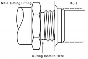
As the name implies, these O-Rings are used to seal Straight Threaded Tube Fittings. As with other O-Rings in static application designs, they make a seal between two mating components. Unlike most O-Rings, they are not completely housed in a rectangular groove or gland. The threaded male tubing fitting does contain a radiused partial groove that retains the O-Ring. The mating part, typically a valve or cylinder port, has a chamfered face that compresses the O-Ring diagonally. The straight threads of both components allow the tube fitting to set completely, causing the O-Ring to be nearly fully compressed. This technique is often referred to as an O-Ring Boss system.
Straight Thread Tube fittings are often used in relatively high pressure applications, so most often a 90 durometer NBR or FKM O-Ring is specified. They can be manufactured in a range of hardnesses and in most common rubber seal polymers however.
English/American System
A number of American Military and Commercial specifications describe the design of the fitting and flange, as well as the O-Rings. The O-Rings most commonly referred to now fall under the AS 568 O-Ring specification and are known as the -9(XX) series O-Rings. With the exception of the -901, the last two numbers of the O-Ring dash number indicate which tube size (in 16ths of an inch) the fittings and seal are used for. Thus, a -906 O-Ring is used on a 3/8” OD tube fitting and a -916 is used on a 1” OD tube fitting. O-Rings are designated for corresponding tube fittings up to 2” OD.
Metric System
Straight Thread Metric connections use similar fittings. One popular system is defined by ISO 6149. Fitting, Port, and O-Ring designs are outlined by this specification. Unlike the American system, ISO 6149 sizes are defined by the port thread size, rather than the tube OD. 13 different sizes are defined ranging from M8 x 1 to M60 x 2.
Leave A Comment
You must be logged in to post a comment.